
Page 17 - TURNING CATALOG p255-458
P. 17
OAL GROOVE-TURN
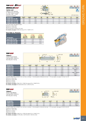
TGPAD-JHP OAH HF
Adapters with Channels WB_2
for High-Pressure Coolant LH CDX WF Bar Max
Carrying TGMF / TGMP WB CW
Groove-Turn Inserts Left-hand shown
Designation CWN(1) CWX(2) CDX(3) WF WB WB_2 LH OAL HF OAH
9.00 4.00 2.40 5.2 12.7 37.20 24.0 30.00
TGPAD 3R/L-T9-JHP 3.00 3.00 16.00 3.50 3.40 5.2 17.2 41.70 24.0 30.00
TGPAD 4R/L-T16-JHP 4.00 5.00 16.00 3.00 4.40 5.2 17.2 41.70 24.0 30.00
5.00 5.00 22.00 3.50 5.00 6.0 23.2 47.10 24.0 32.00
TGPAD 5R/L-T16-JHP 6.00 6.35
TGPAD 6R/L-T22-JHP
• For user guide, see pages 419-436
(1) Minimum cutting width
(2) Maximum cutting width
(3) Grooving depth is limited by the insert
For inserts, see pages: TGMF (full radius) (272) • TGMF/P (272)
Flow Rate vs. Pressure 70 Bar 100 Bar 140 Bar
Flow Rate Flow Rate Flow Rate
Designation (liters/min) (liters/min) (liters/min)
tgpad 3R/L-T9-JHP
tgpad 4R/L-T16-JHP 11-17 17-23 23-26
tgpad 5R/L-T16-JHP 20-25 25-31 31-34
tgpad 6R/L-T22-JHP 27-33 33-39 39-43
30-35 35-41 41-44
TGHN-D OHN-OHX CWN-CWX
Double-Ended Blades OAL
Carrying Utility Inserts for HF H
Grooving and Turning WB
Designation H CWN(1) CWX(2) OHN(3) OHX(4) HF OAL WB Insert
TGMF 3
TGHN 26-3D 26.0 3.00 3.00 10.0 15.0 21.4 110.00 2.40 TGMF 4, TGMF/P 5
TGHN 26-4D 26.0 4.00 5.00 10.0 15.0 21.4 110.00 3.20 TGMF/P 5
26.0 5.00 5.00 10.0 20.0 21.4 110.00 4.00 TGMF 3
TGHN 26-5D TGMF 4, TGMF/P 5
TGMF/P 5
TGHN 32-3D 32.0 3.00 3.00 10.0 18.0 24.8 150.00 2.40 TGMF 6
TGHN 32-4D 32.0 4.00 5.00 12.0 21.0 24.8 150.00 3.20
TGHN 32-5D 32.0 5.00 5.00 12.0 26.0 24.8 150.00 4.00
TGHN 32-6D 32.0 6.00 6.35 16.0 26.0 24.8 150.00 5.20
• Use the drilled holes on blade for min. and max. overhang • Grooving depth is limited by the insert • For user guide, see pages 419-428, 432-436
(1) Minimum cutting width
(2) Maximum cutting width
(3) Minimum overhang
(4) Maximum overhang
For inserts, see pages: TGMA (272) • TGMF (full radius) (272) • TGMF/P (272)
For holders, see pages: SGTBU/SGTBN (616) • UBHCR/L (618)
TGHN-S OHN-OHX CWN-CWX
Single-Ended Blades
Carrying Utility Inserts for HF H
Grooving and Turning OAL WB
Designation H CWN(1) CWX(2) OHN(3) OHX(4) HF OAL WB Insert
48.30 2.40 TGMF 3
TGHN 32-3S 32.0 3.00 3.00 10.0 18.0 24.8 54.00 4.00 TGMF/P 5
TGHN 32-5S 55.70 5.20 TGMF 6
TGHN 32-6S 32.0 5.00 5.00 12.0 25.0 24.8
271
32.0 6.00 6.35 16.0 25.0 24.8
• Use the drilled holes on blade for min. and max. overhang • Grooving depth is limited by the insert • For user guide, see pages 419-428, 432-436
(1) Minimum cutting width
(2) Maximum cutting width
(3) Minimum overhang
(4) Maximum overhang
For inserts, see pages: TGMA (272) • TGMF (full radius) (272) • TGMF/P (272)
For holders, see pages: C#-TBU (623) • IM-TBU (633) • UBHCR/L (618)